
If your Ender 5 Max prints show layer inconsistencies that disappear when the heated bed is turned off, the root cause is electrical noise and poor grounding — not a mechanical issue. Five steps: check Live/Neutral polarity at your wall outlet or power strip, set pwm_cycle_time = 0.3 in printer.cfg, add PE grounding wires to the bed plate and toolhead cage, then recalibrate PID for nozzle and bed.
Table of Contents

Before and after
⚠️ Disclaimer
The modifications described in this tutorial involve working with mains voltage (110V/230V AC) electrical components. Improper handling of mains voltage can cause serious injury, death, or fire.
By following this tutorial, you acknowledge that:
- You perform all modifications at your own risk
- The author accepts no responsibility for any damage, injury, or loss resulting from the application of this guide
- This tutorial is provided as-is, without any warranty of any kind
- Working inside your printer’s electrical compartment may void your warranty
- If you are not confident working with mains voltage, consult a qualified electrician
- Always unplug the printer from the wall before opening any electrical compartment or touching any wiring
- Always verify the printer is fully de-energized before starting any work — use a multimeter to confirm
The author cannot be held liable for any direct, indirect, incidental or consequential damages arising from the use or misuse of the information provided in this tutorial.
Root Cause Explained
The Ender 5 Max uses a 400×400mm AC-powered heated bed. Unlike smaller printers with DC beds, this bed switches high-voltage AC current on and off at a PWM frequency controlled by a MOSFET.
Every time the MOSFET switches, it generates an electromagnetic pulse that propagates through the printer’s frame, wiring, and motion system. On a CoreXY architecture like the Ender 5 Max, both X and Y motors are always active during a move — making the system particularly sensitive to any electrical noise on the frame.
Two structural factors amplify this noise:
- The default PWM frequency (typically 10Hz) creates sharp, high-energy switching spikes
- Ungrounded metal parts (bed plate, toolhead cage) act as antennas, picking up and re-radiating that noise directly into the signal cables running alongside them
This last point is made significantly worse by the printer’s construction: the X axis and toolhead are mounted on POM (polyoxymethylene) plastic sliders, which are electrically insulating. This completely isolates the X axis rail and the toolhead cage from the rest of the aluminum frame — they float electrically with no path to ground. The X axis effectively becomes a large receiving antenna, picking up all the electromagnetic noise generated by the bed and coupling it directly into the stepper motor cables and sensor wiring running alongside it.
A third factor can make things dramatically worse: inverted Live/Neutral polarity at the wall outlet puts the bed heating element — and the aluminum bed plate — at mains potential, massively increasing radiated noise. This is a separate safety issue that must be checked and fixed first.
The result: the stepper drivers receive corrupted step signals during bed switching cycles, causing the slight but visible layer shifts you observe. The symptom disappears with the bed off simply because the noise source is eliminated — not because the motion system is fine.
Step 1 — Check Live/Neutral Wire Polarity
Verify that the Live wire (L — brown) and Neutral wire (N — blue) are not swapped at the power inlet.
⚠️ Depending on your country, some wall outlets are not polarized, meaning you can plug the printer in either orientation — and one of them is wrong.
If inverted, the printer’s metal frame becomes electrically noisy relative to ground, which directly interferes with the motion system and causes layer artifacts.
🔴 Safety hazard: When Live and Neutral are swapped, the heated bed remains directly connected to the Live wire even when switched off. This means the bed surface is at mains voltage potential and touching it — or any connected metal part — can result in electric shock. Always verify polarity before operating the printer.
💀 Critical failure risk: The heated bed is controlled by a MOSFET. MOSFETs can and do fail — and when they fail, they typically fail short-circuit, meaning the bed becomes permanently powered with no software control. If the Live/Neutral polarity is inverted at that moment, the entire aluminum frame of the printer goes live at mains voltage. This is a potentially lethal hazard and a serious fire risk.
Recommended tool: Use an outlet polarity tester (also called a socket tester) to instantly verify your wall outlet wiring. They cost around $5 and plug directly into the outlet — no tools required. Every maker/printer owner should have one.
How to fix inverted polarity: The solution does not require any modification to the printer itself. Instead, check the following:
- Try a different wall outlet in another room — some outlets may be wired incorrectly
- If using a power strip or surge protector, try replacing it or plugging directly into the wall
- If the problem persists across multiple outlets, your electrical installation may be incorrectly wired — consult a qualified electrician
⚠️ Never attempt to modify the printer’s power inlet or swap internal wires to compensate for an inverted outlet. Fix the problem at the source.
Shopping List — Step 1
Phase Tester Screwdriver (Bosch Professional)
Buy on Amazon

223.9V AC measured on the printer frame
The bed plate is directly at mains voltage when Live/Neutral polarity is inverted.

The IEC C13 power connector on the Ender 5 Max
N (Neutral), E (Earth) and L (Live) pins are labeled. Verify your cable matches these positions.
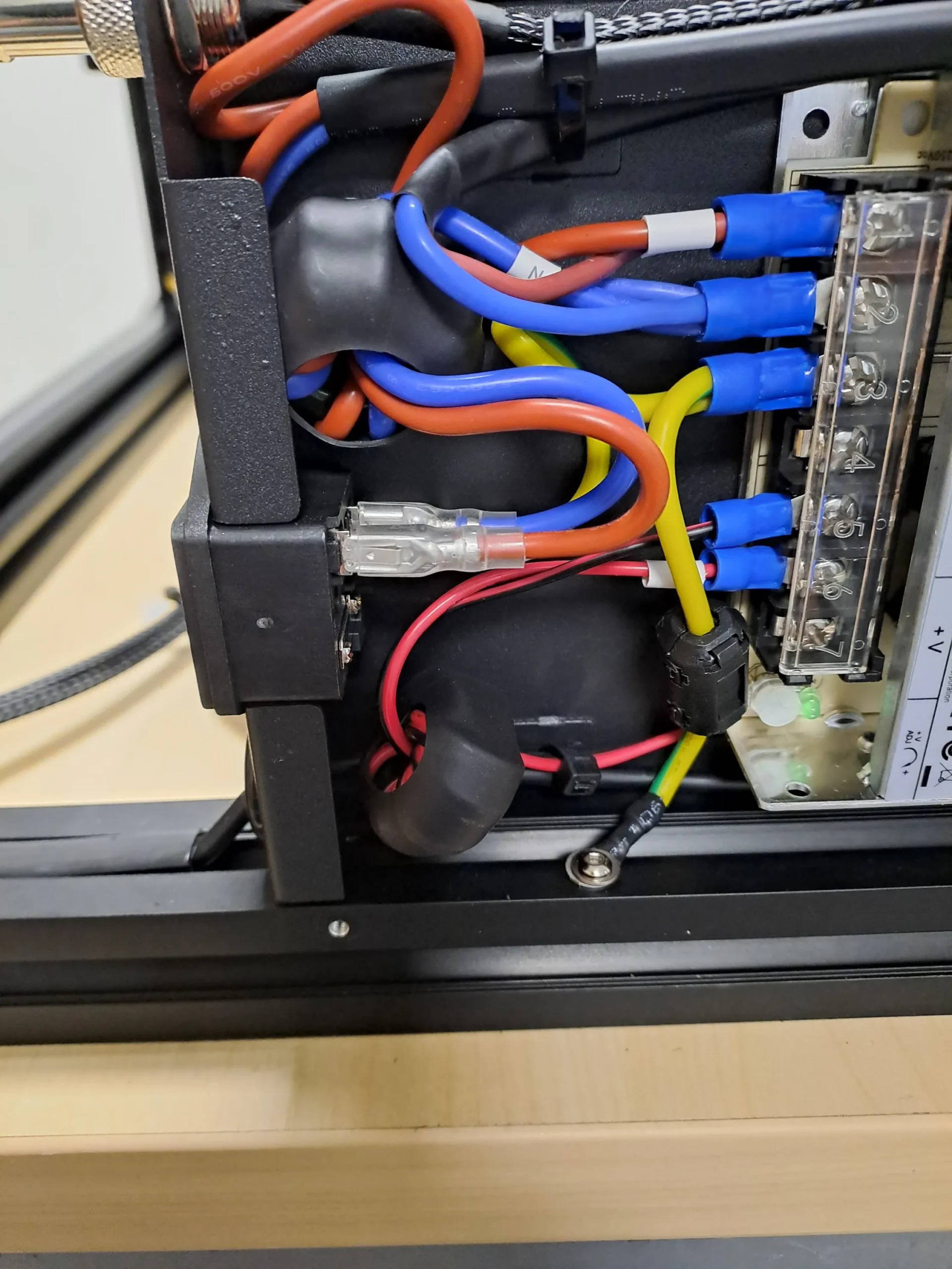
Inside the electrical compartment
Red (Live), blue (Neutral) and yellow/green (PE) wiring. The yellow/green PE wire is the grounding reference for all fixes in this tutorial.
Step 2 — Set PWM Cycle Time on the Heated Bed
Prerequisites
For Option A (Fluidd/Mainsail):
- Enable root access on the Nebula Pad, then install Helper Script, Moonraker, and Fluidd or Mainsail
→ Everything is covered in the Creality Helper Script by Guilouz — follow the instructions in order from the README - Access the web interface from any browser on your local network:
- Fluidd:
http://192.168.XX.XXX:4408 - Mainsail:
http://192.168.XX.XXX:4409
Replace
192.168.XX.XXXwith your Nebula Pad’s IP address (visible in the Nebula Pad network settings). - Fluidd:
For Option B (SSH):
- Enable root access on the Nebula Pad
- An SSH client on your computer — Terminal on macOS/Linux, or PowerShell on Windows (built-in, no installation required)
Edit printer.cfg
Option A — Via Fluidd or Mainsail (web interface)
- In Fluidd or Mainsail, open the Configuration menu (top left)
- Click on
printer.cfgto open it in the editor - Locate the
[heater_bed]section and addpwm_cycle_time = 0.3to it. Do not duplicate the[heater_bed]header — just add the new line inside the existing section:
[heater_bed]
# ... your existing heater_bed parameters ...
pwm_cycle_time = 0.3- Click Save & Restart
Option B — Via SSH (command line)
This method works even if Fluidd/Mainsail is not yet installed, as long as root access is enabled.
- Connect to the Nebula Pad via SSH — replace
192.168.XX.XXXwith your Nebula Pad’s IP address:
ssh root@192.168.XX.XXX- Run the following command to add
pwm_cycle_time = 0.3automatically to the[heater_bed]section:
sed -i '/[heater_bed]/a pwm_cycle_time = 0.3' /usr/data/printer_data/config/printer.cfg- Verify the change was applied correctly:
grep -A 5 'heater_bed' /usr/data/printer_data/config/printer.cfg- Reboot the Nebula Pad to apply the change:
rebootThis slows down the bed’s PWM switching frequency from the default to ~3Hz, significantly reducing the energy of each switching spike and the noise injected into the frame and wiring.
🔴 Safety reminder for Steps 3 and 4: Always unplug the printer from the wall before opening any panel or touching any wiring. Use a multimeter to verify the printer is fully de-energized before starting.
Step 3 — Ground the Aluminum Bed Plate
This fix eliminates the floating ground potential on the bed plate, which acts as a large antenna radiating electrical noise directly into the motion system.
You will need:
- Silicone insulated cable, 1.5 mm² (15 AWG) section — 2 meters is sufficient (link)
- Ferrule + ring terminal connectors + crimping tool (link)
- Zip ties, 3×100mm (link) — you will need to cut the existing ones to open the cable sleeve, then replace them once the new wire is routed
Shopping List — Step 3
Silicone Cable 1.5mm² (15 AWG) — 2m
Buy on AliExpress
Ferrule + Ring Terminal Connectors & Crimping Tool
Buy on AliExpress
Zip Ties 3×100mm
Buy on AliExpress
Connection steps:
- Attach the wire to the bed plate — crimp a ferrule on one end and connect it to one of the small screws that fixes the heating element to the aluminum plate

PE wire crimped with a ferrule terminal, connected to a heating element fixing screw on the aluminum bed plate. - Route the wire through the cable sleeve — cut the existing zip ties to open the braided sleeve, then feed the new wire alongside the existing bed wiring. You will also need to remove the adhesive tape at the cable gland on the bottom of the machine. Once the wire is in place, secure everything with new zip ties.
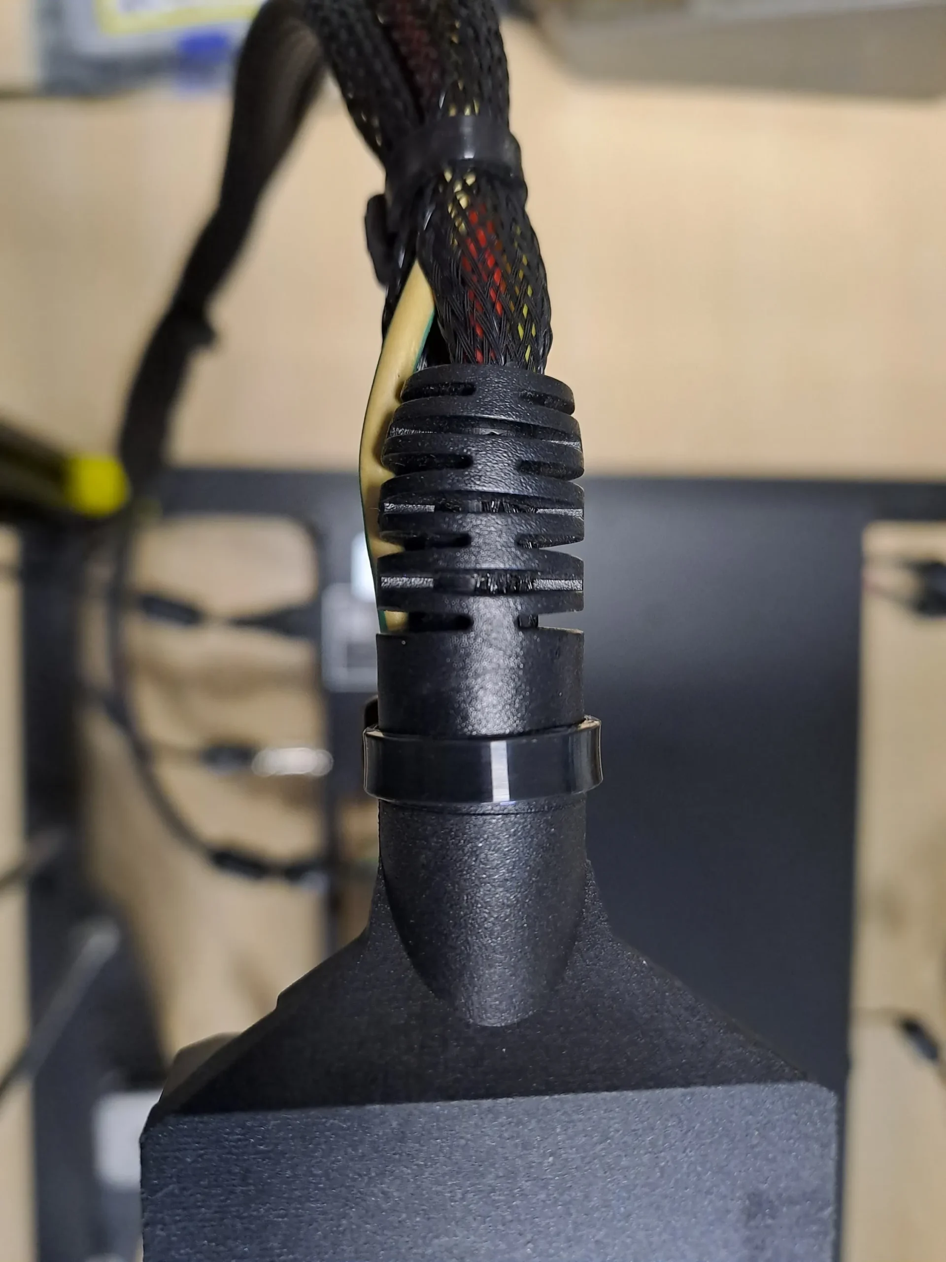
Yellow/green PE wire routed through the braided cable sleeve alongside the bed wiring, secured with new zip ties. 
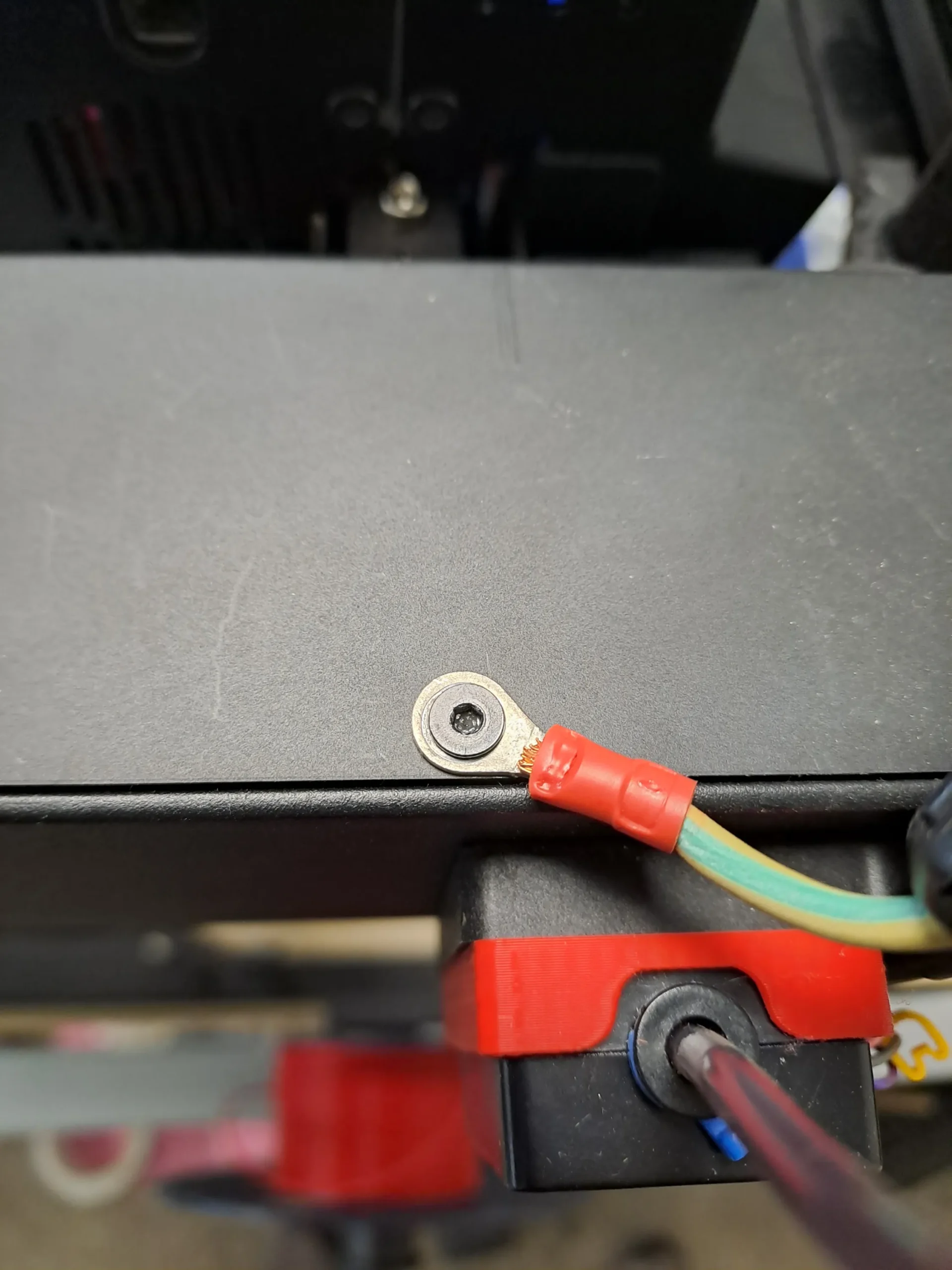
Cable passing through the cable gland at the bottom of the machine — the adhesive tape must be removed to thread the new wire through. - Connect to the PE terminal — inside the electrical compartment, crimp a ring terminal on the other end and bolt it directly onto the aluminum frame extrusion at the PE connection point

Ring terminal bolted to the aluminum frame extrusion, connected to the original PE terminal block.
Step 4 — Ground the Toolhead Metal Cage
The toolhead metal cage is a floating conductor that runs alongside all signal cables. Bonding it to the printer frame eliminates the noise it picks up and re-radiates into the stepper and sensor wiring.
You will need:
- Silicone insulated cable, 1.5 mm² (15 AWG) section — 2 meters is sufficient (link). Make sure to leave enough slack to cover the full travel range of the toolhead without tension
- Ferrule + ring terminal connectors + crimping tool (link)
- Custom printed toolhead cable clips (link)
Shopping List — Step 4
TO BUY :
Silicone Cable 1.5mm² (15 AWG) — 2m
Buy on AliExpressFerrule + Ring Terminal Connectors & Crimping Tool
Buy on AliExpress
TO PRINT :
Custom Toolhead Cable Clips (3D Print)
Download Free
You may need from 10 to 12 units. I designed this cable clip specifically for this application. It took several attempts to find the right adjustments so that it would hold securely without damaging the cable.
- Attach the wire to the toolhead cage — crimp a ferrule on one end and connect it to one of the toolhead screws
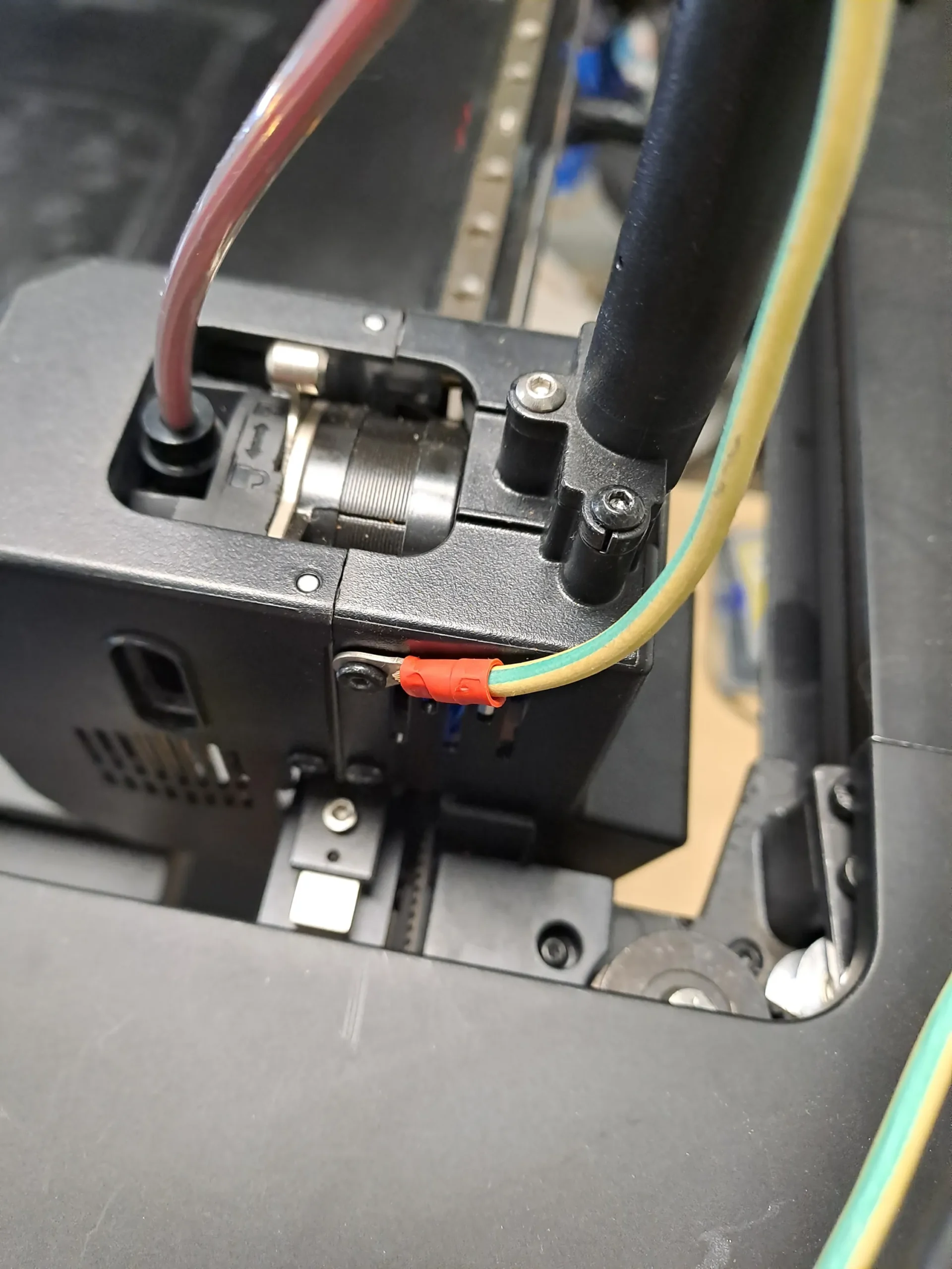
PE wire crimped with a ferrule terminal, connected to a toolhead cage screw. The wire runs alongside the existing toolhead cable. - Route the wire along the toolhead cable — use the custom printed clips to keep the PE wire neatly bundled with the toolhead cable along its full travel path
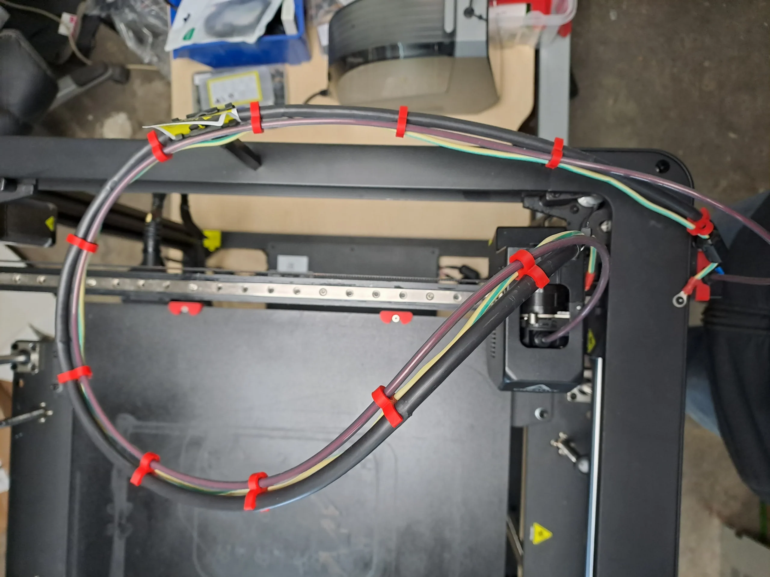
PE wire routed along the toolhead cable and secured with custom printed red clips. The clips ensure the wire follows the cable’s movement without slack or tension. - Connect to the printer frame — crimp a ring terminal on the other end and bolt it to a screw on the aluminum frame of the printer
Ring terminal bolted to the printer’s aluminum frame, completing the PE bond between the toolhead cage and the main structure.
Step 5 — Recalibrate PID for Nozzle and Bed
After these modifications, a PID recalibration is recommended for two reasons:
- The
pwm_cycle_timechange (Step 2) directly affects how the bed heater is driven — the PID controller was tuned for the original switching frequency and needs to be re-optimized for the new one. This is the main reason to recalibrate the bed PID. - The nozzle PID is less directly affected by these changes, but recalibrating it is good practice after any significant intervention on the printer, to ensure stable temperature control and rule out any thermal regulation issue contributing to print artifacts.
A poorly tuned PID results in temperature oscillations that can cause — you guessed it — layer inconsistencies.
How to recalibrate on the Nebula Pad
The PID calibration is performed directly from the Nebula Pad touchscreen interface:
For the nozzle:
- On the Nebula Pad, go to Settings → Expert Mode → PID Nozzle
For the bed:
- On the Nebula Pad, go to Settings → Expert Mode → PID HOTBED
⚠️ Run the PID calibration with the printer in its normal operating environment — top cover on if you normally print with it closed, and at room temperature. Conditions at calibration time will affect the result.
Compatible Printers
This tutorial was written and tested on the Creality Ender 5 Max.
The root cause and fixes may apply to other FDM printers with an AC-powered heated bed, but this has not been verified. If you have confirmed this fix works on another model, feel free to leave a comment below.
Tutorial by Christian KELHETTER — feel free to share and adapt with credit.
v1.0 — March 2026